huawei network ekipmanlarında trafik istatiklerini toplamak
network ekipmanlarında trafik verisini toplamak genellikle üreticiye göre değişmekle birlikte ya pasif haldedir yada üreticinin belirlemiş olduğu bir değerlerle çalışmaktadır.
üreticiler veri toplama işi için ayrı bir mimari yapısı kullanmıyor / geliştirmediyse bu süreler genellikle sadece ev kullanıcısının işini yarayacaktır.
çünkü network ekipmanın üzerindeki arayüz sayısı fazla ve sürede kısa olursa cpu ve ram de ilave bir artışa neden olacaktır. bu nedenden dolayı sürelern kısaltılması öncesi cpu ve ram değerlerini takip etmek faydalı olacaktır.
huawei network ekipmanlarında arayüz altında
set flow-stat interval interval-timeile bu degeri değiştirebiliyorsunuz. buradaki interval-time 10 ile 600 arasında 10 katları olmak zorundadır. huaweinin bir çok ekipmanında varsayılan değeri 300 dur. huawei kritik veri gözlemlenmeyecek varsayılan degerlerde veya üstünde olmasını önermekte.
<Huawei> system-view
[Huawei] interface gigabitethernet 0/0/1
[Huawei-GigabitEthernet0/0/1] set flow-stat interval 400
0/0/1 için 400 e set edelim ve arayüzün durumuna bakalım.
<Huawei> display interface gigabitethernet 0/0/1
GigabitEthernet0/0/1 current state : UP
Line protocol current state : UP
Description:lineate-port-0
Switch Port, PVID :    1, TPID : 8100(Hex), The Maximum Frame Length is 9216
IP Sending Frames' Format is PKTFMT_ETHNT_2, Hardware address is 1047-80ac-cc60
Last physical up time   : 2020-02-10 01:46:35 UTC+08:00
Last physical down time : 2020-02-10 01:46:30 UTC+08:00
Current system time: 2020-02-11 11:11:36+08:00
Port Mode: COMMON COPPER
Speed : 1000,  Loopback: NONE
Duplex: FULL,  Negotiation: ENABLE
Mdi   : AUTO
Last 400 seconds input rate 80 bits/sec, 0 packets/sec
Last 400 seconds output rate 152 bits/sec, 0 packets/sec
Input peak rate 57064 bits/sec,Record time: 2020-02-10 07:43:17
Output peak rate 39872 bits/sec,Record time: 2020-02-11 11:11:36

Input:  71004 packets, 9224321 bytes
  Unicast:              20023,  Multicast:               49102
  Broadcast:             1879,  Jumbo:                       0
  Discard:                  0,  Total Error:                 0

  CRC:                      0,  Giants:                      0
  Jabbers:                  0,  Throttles:                   0
  Runts:                    0,  Alignments:                  0
  Symbols:                  0,  Ignoreds:                    0
  Frames:                   0

Output:  20221 packets, 1679706 bytes
  Unicast:              19989,  Multicast:                   0
  Broadcast:              232,  Jumbo:                       0
  Discard:                  0,  Total Error:                 0

  Collisions:               0,  ExcessiveCollisions:         0
  Late Collisions:          0,  Deferreds:                   0

    Input bandwidth utilization threshold : 100.00%
    Output bandwidth utilization threshold: 100.00%
    Input bandwidth utilization  : 0.01%
    Output bandwidth utilization : 0.01%
yukarıdaki çıktıda 400 saniyede bir örnekleme yapıldığı ve 90/152 bits/sec lik trafik olduğu görülmektedir.
Last 400 seconds input rate 80 bits/sec, 0 packets/sec Last 400 seconds output rate 152 bits/sec, 0 packets/sec huawei network ekipmanlarında alarm nedeniyle kapanmış olan arayüzlerin açılması
bir çok router ve switchte herhangi bir arayüz üzerindeki servislerde veya portta fiziksel hataların tespiti ile o arayüz üzerindeki servislerin / trafiğin daha fazla etkilenmemesi için arayüzü kapatabilirsiniz.
huawei network ekipmanlarında benzer şekilde kapatılmış arayüzlerin tespitini yapmak için farklı yöntemler mevcut.
display trapbuffer ve display logbuffer ile log incelemesi yapılabilir. display interface brief ile loop v.b. durumlar gözlemlenebilir.
en temel olanı ise arayüze doğrudan bakmak.
[test_router-GigabitEthernet1/0/1]display interface GigabitEthernet 1/0/1
GigabitEthernet1/0/1 current state : Port-alarm DOWN
Line protocol current state : DOWN
Link quality grade : --
Description:test-interface
Route Port,The Maximum Transmit Unit is 9212
Internet Address is 11.12.13.17/31
IP Sending Frames' Format is PKTFMT_ETHNT_2, Hardware address is bc3d-39ef-f236
The Vendor PN is MTRS-02X13-G
The Vendor Name is HG GENUINE
Port BW: 10G, Transceiver max BW: 10G, Transceiver Mode: SingleMode
WaveLength: 1310nm, Transmission Distance: 10km
Rx Power: -2.09dBm, Warning range: [-14.40,  0.50]dBm
Tx Power: -40.00dBm, Warning range: [-8.20,  0.50]dBm
Loopback:none, LAN full-duplex mode, Pause Flowcontrol:Receive Enable and Send Enable
Last physical up time   : 2020-08-22 14:27:21 UTC+03:00
Last physical down time : 2020-08-22 14:27:23 UTC+03:00
Current system time: 2020-08-22 17:31:33+03:00
Statistics last cleared:2020-08-22 16:32:36
    Last 10 seconds input rate: 0 bits/sec, 0 packets/sec
    Last 10 seconds output rate: 0 bits/sec, 0 packets/sec
    Input: 0 bytes, 0 packets
    Output: 0 bytes, 0 packets
    Input:
      Unicast: 0 packets, Multicast: 0 packets
      Broadcast: 0 packets, JumboOctets: 0 packets
      CRC: 0 packets, Symbol: 0 packets
      Overrun: 0 packets, InRangeLength: 0 packets
      LongPacket: 0 packets, Jabber: 0 packets, Alignment: 0 packets
      Fragment: 0 packets, Undersized Frame: 0 packets
      RxPause: 0 packets
    Output:
      Unicast: 0 packets, Multicast: 0 packets
      Broadcast: 0 packets, JumboOctets: 0 packets
      Lost: 0 packets, Overflow: 0 packets, Underrun: 0 packets
      System: 0 packets, Overrun: 0 packets
      TxPause: 0 packets
      Unknown Vlan: 0 packets
    Input bandwidth utilization  :    0%
    Output bandwidth utilization :    0%
veya
[test_router-GigabitEthernet1/0/1]display interface phy-option GigabitEthernet 1/0/1
GigabitEthernet1/0/1
Port Physical Status    :DOWN
Physical Down Reason    :PORT_ALARM_DOWN
Loopback                :none
Duplex mode             :full-duplex
Pause Flowcontrol:
Receive                 :Enable
Send                    :Enable
SFP imformation:
The Vendor PN is MTRS-02X13-G
The Vendor Name is HG GENUINE
Port BW: 10G, Transceiver max BW: 10G, Transceiver Mode: SingleMode
WaveLength: 1310nm, Transmission Distance: 10km
Rx Power: -2.08dBm, Warning range: [-14.40,  0.50]dBm
Tx Power: -40.00dBm, Warning range: [-8.20,  0.50]dBm
yukarıdaki örneklerde
GigabitEthernet1/0/1 current state : Port-alarm DOWN
Tx Power: -40.00dBm, Warning range: [-8.20,  0.50]dBm

Port Physical Status    :DOWN
Physical Down Reason    :PORT_ALARM_DOWN
arayüzün alarm nedeniyle down olduğu ve doğal olarak tx = -40 olduğu görülmektedir.
bu örnekte arayüz altında hata olmadığı görülüyor. alarmlar temizlenmiş v.b. olabilir. arayüzün neden kapanmış olduğuna bakalım.
[test_router-GigabitEthernet1/0/1]display  port-error-info  interface GigabitEthernet 1/0/1
GigabitEthernet1/0/1 port-error information
================================================================================
 input-error                            | output-error
--------------------------------------------------------------------------------
 trap enable    : Yes                   | trap enable    : Yes
 trigger down   : No                    | trigger down   : No
 alarm status   : No                    | alarm status   : No
 threshold high : 1000                  | threshold high : 1000
 threshold low  : 100                   | threshold low  : 100
 interval       : 10    sec.            | interval       : 10    sec.
 stat(h)        : 0                     | stat(h)        : 0
 stat(l)        : 0                     | stat(l)        : 0
================================================================================
 crc-error                              | symbol-error
--------------------------------------------------------------------------------
 trap enable    : Yes                   | trap enable    : Yes
 trigger down   : Yes                   | trigger down   : No
 alarm status   : No                    | alarm status   : No
 threshold high : 3                     | threshold high : 1000
 threshold low  : 3                     | threshold low  : 100
 percent        : 0                     | N/A            : N/A
 interval       : 10    sec.            | interval       : 10    sec.
 stat(h)        : 0                     | stat(h)        : 0
 stat(l)        : 0                     | stat(l)        : 0
[test_router-GigabitEthernet1/0/1]
arayüz için 4 alarm kontrolün aktif olduğu görülmektedir. çıktıya baktığımızda
crc-error
trap enable    : Yes
trigger down   : Yes
crc hataları nedeniyle tetiklendiği görülmektedir. ilk önce portun kapanmasına neden olan alarmlar giderilmeli. alarm nedeni giderildikten sonra yapılması gereken için port üzerindeki alarmların clear edilmesi gerekmekte.
bunun nasıl yapılacağını
huawei routerlarda interface üzerinde alarm sayısını sıfırlama
başlıklı yazıda yazmıştım. alarmları sıfırladıktan sonra arayüzün aktif hala gelmesi gerekiyor. eğer aktif olmaz ise portu restart yapmak faydalı olabilir.
[test_router-GigabitEthernet1/0/1]restart
Huawei Wi-Fi 6 (802.11ax) Technology White Paper
huawei ağ ekipmanlarında basit martini vpls uygulaması
aşağıdaki topoloji üzerinde huawei ağ ekipmanlarını kullanarak basit bir mpls martini vpls örneği yapalım.
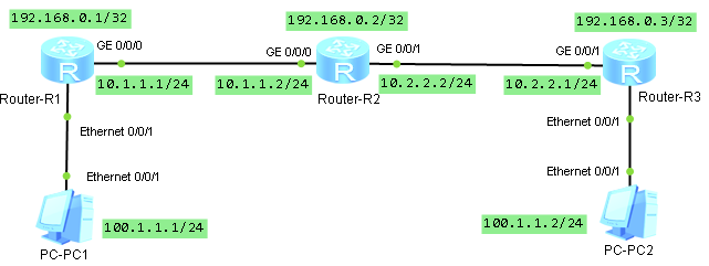
öncelikle loopback ve ip tanımlarını sırasıyla yapalım.
sysname R1

interface GigabitEthernet0/0/0
 ip address 10.1.1.1 255.255.255.0

interface LoopBack0
 ip address 192.168.0.1 255.255.255.255
sysname R2
interface GigabitEthernet0/0/0
ip address 10.1.1.2 255.255.255.0
interface GigabitEthernet0/0/1
ip address 10.2.2.2 255.255.255.0
interface LoopBack0
ip address 192.168.0.2 255.255.255.255sysname R3
interface GigabitEthernet0/0/1
ip address 10.2.2.1 255.255.255.0
interface LoopBack0
ip address 192.168.0.3 255.255.255.255tüm arayüzler aktif olduktan sonra örnekte ospf yönlendirme protokolünü kullanacağımız için yönlendiriciler üzerinde ospf leri aktif etmek için gerekli yapılandırmasını yapalım.
sysname R1
ospf 1
 area 0.0.0.0
  network 192.168.0.1 0.0.0.0
  network 10.1.1.0 0.0.0.255
sysname R2
ospf 1
area 0.0.0.0
network 192.168.0.2 0.0.0.0
network 10.1.1.0 0.0.0.255
network 10.2.2.0 0.0.0.255sysname R3
ospf 1
area 0.0.0.0
network 10.2.2.0 0.0.0.255
network 192.168.0.3 0.0.0.0ospf de aktif olduktan sonra mpls tanımlarına başlayabiliriz. tüm yönlendiriciler de global de mpls i aktif edelim.
mpls lsr-id 192.168.0.x
mpls
mpls l2vpn
mpls ldp
sonrasında ağımızda yönlendiriciler arasındaki arayüz bağlantıları altında mpls, mpls ldp aktif ediyoruz.
interface GigabitEthernet0/0/x
 mpls
 mpls ldp
en temel kontrolleri yaptık bir sorun görülmüyor. şimdi pc1 – pc2 arasındaki haberleşmenin sağlanması için gerekli yapılandırmaya sıra geldi. öncelikle r1 den r3 , r3 den r1 doğru ldp remote tanımlarını yapmalıyız.
sysname R1
mpls ldp remote-peer ldp_peer_to_r3
 remote-ip 192.168.0.3
sysname R3
mpls ldp remote-peer ldp_peer_to_r1
remote-ip 192.168.0.1şimdi yapabileceğimiz bazı kontrolleri yapalım.
<R1>display  mpls interface
Interface             Status    TE Attr   LSP Count  CRLSP Count Effective MTU
GE0/0/0               Up        Dis       4          0           1500
<R1>
<R1>display mpls ldp session
LDP Session(s) in Public Network
Codes: LAM(Label Advertisement Mode), SsnAge Unit(DDDD:HH:MM)
A '*' before a session means the session is being deleted.
------------------------------------------------------------------------------
PeerID Status LAM SsnRole SsnAge KASent/Rcv
------------------------------------------------------------------------------
192.168.0.2:0 Operational DU Passive 0000:01:45 423/423
192.168.0.3:0 Operational DU Passive 0000:01:53 455/455
------------------------------------------------------------------------------
TOTAL: 2 session(s) Found.[R1]display mpls route-state
Codes: B(BGP), I(IGP), L(Public Label BGP), O(Original BGP), U(Unknow)
--------------------------------------------------------------------------------
Dest/Mask Next-Hop Out-Interface State LSP VRF Type
--------------------------------------------------------------------------------
192.168.0.1/32 127.0.0.1 InLoop0 READY 1 0 I
192.168.0.2/32 10.1.1.2 GE0/0/0 READY 2 0 I
192.168.0.3/32 10.1.1.2 GE0/0/0 READY 2 0 I[R1]display mpls lsp
-------------------------------------------------------------------------------
LSP Information: LDP LSP
-------------------------------------------------------------------------------
FEC In/Out Label In/Out IF Vrf Name
192.168.0.2/32 NULL/3 -/GE0/0/0
192.168.0.2/32 1028/3 -/GE0/0/0
192.168.0.3/32 NULL/1025 -/GE0/0/0
192.168.0.3/32 1029/1025 -/GE0/0/0
192.168.0.1/32 3/NULL -/- şimdi vsi ları oluşturalım. burada dikkat edilmesi gereken en önemli nokta vsi-id lerin aynı olması gerektiğidir.
sysname R1
vsi vsi_for_pc static
 pwsignal ldp
  vsi-id 100
  peer 192.168.0.3
sysname R3
vsi vsi_for_pc static
pwsignal ldp
vsi-id 100
peer 192.168.0.1son aşamaya gelmiş olduk. bilgisayarların bağlı arayüzler için tanımları da tapalım.
sysname R1
interface Ethernet0/0/1
 l2 binding vsi vsi_for_pc
sysname R3
interface Ethernet0/0/1
l2 binding vsi vsi_for_pctüm yapılandırmaları tamamlamış olduk. şimdi bilgisayarlara ip leri girerek erişim kontrolleri yapalım. bilgisayarlarda ağ geçidi olarak karşı bilgisayarın iplerini girelim.
PC>ping 100.1.1.2

Ping 100.1.1.2: 32 data bytes, Press Ctrl_C to break
From 100.1.1.2: bytes=32 seq=1 ttl=128 time=94 ms
From 100.1.1.2: bytes=32 seq=2 ttl=128 time=156 ms
From 100.1.1.2: bytes=32 seq=3 ttl=128 time=62 ms
From 100.1.1.2: bytes=32 seq=4 ttl=128 time=94 ms
From 100.1.1.2: bytes=32 seq=5 ttl=128 time=110 ms

--- 100.1.1.2 ping statistics ---
  5 packet(s) transmitted
  5 packet(s) received
  0.00% packet loss
  round-trip min/avg/max = 62/103/156 ms
yönlendiricilere ait yapılandırmaların tam hali aşağıda yer almaktadır.
sysname R1

mpls lsr-id 192.168.0.1
mpls
mpls l2vpn
mpls ldp

vsi vsi_for_pc static
 pwsignal ldp
  vsi-id 100
  peer 192.168.0.3

mpls ldp remote-peer ldp_peer_to_r3
 remote-ip 192.168.0.3

interface Ethernet0/0/1
 l2 binding vsi vsi_for_pc

interface GigabitEthernet0/0/0
 ip address 10.1.1.1 255.255.255.0
 mpls
 mpls ldp

interface LoopBack0
 ip address 192.168.0.1 255.255.255.255

ospf 1
 area 0.0.0.0
  network 192.168.0.1 0.0.0.0
  network 10.1.1.0 0.0.0.255
sysname R2
mpls lsr-id 192.168.0.2
mpls
mpls ldp
interface GigabitEthernet0/0/0
ip address 10.1.1.2 255.255.255.0
mpls
mpls ldp
interface GigabitEthernet0/0/1
ip address 10.2.2.2 255.255.255.0
mpls
mpls ldp
interface LoopBack0
ip address 192.168.0.2 255.255.255.255
ospf 1
area 0.0.0.0
network 192.168.0.2 0.0.0.0
network 10.1.1.0 0.0.0.255
network 10.2.2.0 0.0.0.255sysname R3
mpls lsr-id 192.168.0.3
mpls
mpls l2vpn
mpls ldp
vsi vsi_for_pc static
pwsignal ldp
vsi-id 100
peer 192.168.0.1
mpls ldp remote-peer ldp_peer_to_r1
remote-ip 192.168.0.1
interface Ethernet0/0/1
l2 binding vsi vsi_for_pc
interface GigabitEthernet0/0/1
ip address 10.2.2.1 255.255.255.0
mpls
mpls ldp
interface LoopBack0
ip address 192.168.0.3 255.255.255.255
ospf 1
area 0.0.0.0
network 10.2.2.0 0.0.0.255
network 192.168.0.3 0.0.0.huawei ağ ekipmanlarında basit ospf uygulaması
ospf detaylarına girmeden huawei ağ ekipmanlarında ospf nasıl kullanabiliriz ve kontrol edebiliriz aşağıdaki örnek topolojide incelemeye çalışalım.
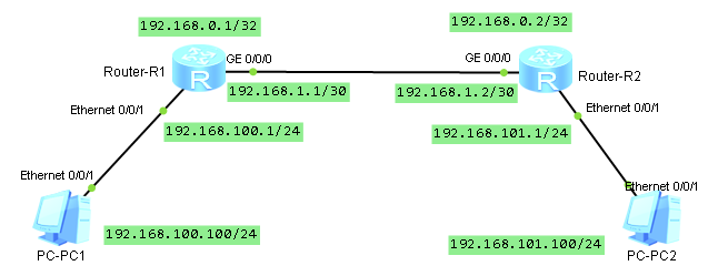
yönlendiriciler üzerine öncelikle arayüz iplerini girelim
sysname R1

router id 192.168.0.1

interface Ethernet0/0/1
 ip address 192.168.100.1 255.255.255.0

interface GigabitEthernet0/0/0
 ip address 192.168.1.1 255.255.255.252

interface LoopBack0
 ip address 192.168.0.1 255.255.255.255
sysname R2
router id 192.168.0.2
interface Ethernet0/0/1
ip address 192.168.101.1 255.255.255.0
interface GigabitEthernet0/0/0
ip address 192.168.1.2 255.255.255.252
interface LoopBack0
ip address 192.168.0.2 255.255.255.255arayüzlerin durumunu kontrol edelim
<R1>display ip interface brief
*down: administratively down
!down: FIB overload down
^down: standby
(l): loopback
(s): spoofing
(d): Dampening Suppressed
The number of interface that is UP in Physical is 4
The number of interface that is DOWN in Physical is 8
The number of interface that is UP in Protocol is 4
The number of interface that is DOWN in Protocol is 8

Interface                         IP Address/Mask      Physical   Protocol
Ethernet0/0/0                     unassigned           down       down
Ethernet0/0/1                     192.168.100.1/24     up         up
GigabitEthernet0/0/0              192.168.1.1/30       up         up
GigabitEthernet0/0/1              unassigned           down       down
GigabitEthernet0/0/2              unassigned           down       down
GigabitEthernet0/0/3              unassigned           down       down
LoopBack0                         192.168.0.1/32       up         up(s)
NULL0                             unassigned           up         up(s)
Serial0/0/0                       unassigned           down       down
Serial0/0/1                       unassigned           down       down
Serial0/0/2                       unassigned           down       down
Serial0/0/3                       unassigned           down       down
tüm arayüzlerimiz aktif durumda. yönlendirme tablolarını da kontrol edelim
<R1>display ip routing-table
Route Flags: R - relay, D - download to fib
------------------------------------------------------------------------------
Routing Tables: Public
         Destinations : 7        Routes : 7

Destination/Mask    Proto   Pre  Cost      Flags NextHop         Interface

      127.0.0.0/8   Direct  0    0           D   127.0.0.1       InLoopBack0
      127.0.0.1/32  Direct  0    0           D   127.0.0.1       InLoopBack0
    192.168.0.1/32  Direct  0    0           D   127.0.0.1       LoopBack0
    192.168.1.0/30  Direct  0    0           D   192.168.1.1     GigabitEthernet0/0/0
    192.168.1.1/32  Direct  0    0           D   127.0.0.1       GigabitEthernet0/0/0
  192.168.100.0/24  Direct  0    0           D   192.168.100.1   Ethernet0/0/1
  192.168.100.1/32  Direct  0    0           D   127.0.0.1       Ethernet0/0/1
R1 üzerinde görüleceği üzere pc1 den pc2 ye ulaşmak istersek R1 üzerinden gerekli yönlendirme yapılamayacaktır. bu yönlendirme işlemini ospf ile yapmaya çalışalım..
R1 üzerine area 0 oluşturalım ve cihaz üzerindeki tüm networkleri ekleyelim
[R1]ospf 1 router-id 192.168.0.1
[R1-ospf-1]area 0
[R1-ospf-1-area-0.0.0.0]network 192.168.100.0 0.0.0.255
[R1-ospf-1-area-0.0.0.0]network 192.168.1.0 0.0.0.3
[R1-ospf-1-area-0.0.0.0]network 192.168.0.1 0.0.0.0
r1 üzerinde ospf için gerekli ayarları yaptıktan sonra gerekli kontrolleri sağlayalım.
[R1]display  ospf lsdb

	 OSPF Process 1 with Router ID 192.168.0.1
		 Link State Database

		         Area: 0.0.0.0
 Type      LinkState ID    AdvRouter          Age  Len   Sequence   Metric
 Router    192.168.0.1     192.168.0.1        440  60    80000005       1
<R1>display ospf nexthop
OSPF Process 1 with Router ID 192.168.0.1
Routing Nexthop information
Next hops:
Address Type Refcount IntfAddr Intf Name
----------------------------------------------------------------
192.168.100.1 Local 1 192.168.100.1 Ethernet0/0/1
192.168.1.1 Local 1 192.168.1.1 GigabitEthernet0/0/0
192.168.0.1 Local 1 192.168.0.1 LoopBack0 <R1>display ospf routing
OSPF Process 1 with Router ID 192.168.0.1
Routing Tables
Routing for Network
Destination Cost Type NextHop AdvRouter Area
192.168.0.1/32 0 Stub 192.168.0.1 192.168.0.1 0.0.0.0
192.168.1.0/30 1 Stub 192.168.1.1 192.168.0.1 0.0.0.0
192.168.100.0/24 1 Stub 192.168.100.1 192.168.0.1 0.0.0.0
Total Nets: 3
Intra Area: 3 Inter Area: 0 ASE: 0 NSSA: 0 [R1]display ip routing-table
Route Flags: R - relay, D - download to fib
------------------------------------------------------------------------------
Routing Tables: Public
Destinations : 7 Routes : 7
Destination/Mask Proto Pre Cost Flags NextHop Interface
127.0.0.0/8 Direct 0 0 D 127.0.0.1 InLoopBack0
127.0.0.1/32 Direct 0 0 D 127.0.0.1 InLoopBack0
192.168.0.1/32 Direct 0 0 D 127.0.0.1 LoopBack0
192.168.1.0/30 Direct 0 0 D 192.168.1.1 GigabitEthernet0/0/0
192.168.1.1/32 Direct 0 0 D 127.0.0.1 GigabitEthernet0/0/0
192.168.100.0/24 Direct 0 0 D 192.168.100.1 Ethernet0/0/1
192.168.100.1/32 Direct 0 0 D 127.0.0.1 Ethernet0/0/1şimdi R2 üzefinde ospf konfigürasyonu yapmaya başlayalım. ilk önce area 0 oluşturalım ve R1 arayünün ip networke ekleyelim ve değişimleri gözlemleyelim
<R1>display ospf lsdb

	 OSPF Process 1 with Router ID 192.168.0.1
		 Link State Database

		         Area: 0.0.0.0
 Type      LinkState ID    AdvRouter          Age  Len   Sequence   Metric
 Router    192.168.0.2     192.168.0.2         35  36    80000003       1
 Router    192.168.0.1     192.168.0.1         31  60    80000009       1
 Network   192.168.1.1     192.168.0.1         31  32    80000002       0
<R1>display ospf routing
OSPF Process 1 with Router ID 192.168.0.1
Routing Tables
Routing for Network
Destination Cost Type NextHop AdvRouter Area
192.168.0.1/32 0 Stub 192.168.0.1 192.168.0.1 0.0.0.0
192.168.1.0/30 1 Transit 192.168.1.1 192.168.0.1 0.0.0.0
192.168.100.0/24 1 Stub 192.168.100.1 192.168.0.1 0.0.0.0
Total Nets: 3
Intra Area: 3 Inter Area: 0 ASE: 0 NSSA: 0 <R1>display ospf nexthop
OSPF Process 1 with Router ID 192.168.0.1
Routing Nexthop information
Next hops:
Address Type Refcount IntfAddr Intf Name
----------------------------------------------------------------
192.168.100.1 Local 1 192.168.100.1 Ethernet0/0/1
192.168.1.1 Local 1 192.168.1.1 GigabitEthernet0/0/0
192.168.0.1 Local 1 192.168.0.1 LoopBack0 <R1>display ip routing-table
Route Flags: R - relay, D - download to fib
------------------------------------------------------------------------------
Routing Tables: Public
Destinations : 7 Routes : 7
Destination/Mask Proto Pre Cost Flags NextHop Interface
127.0.0.0/8 Direct 0 0 D 127.0.0.1 InLoopBack0
127.0.0.1/32 Direct 0 0 D 127.0.0.1 InLoopBack0
192.168.0.1/32 Direct 0 0 D 127.0.0.1 LoopBack0
192.168.1.0/30 Direct 0 0 D 192.168.1.1 GigabitEthernet0/0/0
192.168.1.1/32 Direct 0 0 D 127.0.0.1 GigabitEthernet0/0/0
192.168.100.0/24 Direct 0 0 D 192.168.100.1 Ethernet0/0/1
192.168.100.1/32 Direct 0 0 D 127.0.0.1 Ethernet0/0/1R2 için diğer networkleride ekleyelim. yönlendirme tabloları , lsdb vb deki değişimleri gözlemleyelim.
ospf 1 router-id 192.168.0.2
 area 0.0.0.0
  network 192.168.1.0 0.0.0.3
  network 192.168.0.2 0.0.0.0
  network 192.168.101.0 0.0.0.255
tüm networkleri r2 üzerinde tamamladıktan sonra yönlendirme tablosunu kontrol ederek pc1 den pc2 ye erişimi kontrol edelim.
<R1>display ospf routing

	 OSPF Process 1 with Router ID 192.168.0.1
		  Routing Tables

 Routing for Network
 Destination        Cost  Type       NextHop         AdvRouter       Area
 192.168.0.1/32     0     Stub       192.168.0.1     192.168.0.1     0.0.0.0
 192.168.1.0/30     1     Transit    192.168.1.1     192.168.0.1     0.0.0.0
 192.168.100.0/24   1     Stub       192.168.100.1   192.168.0.1     0.0.0.0
 192.168.0.2/32     1     Stub       192.168.1.2     192.168.0.2     0.0.0.0
 192.168.101.0/24   2     Stub       192.168.1.2     192.168.0.2     0.0.0.0

 Total Nets: 5
 Intra Area: 5  Inter Area: 0  ASE: 0  NSSA: 0
PC>ping 192.168.101.1
Ping 192.168.101.1: 32 data bytes, Press Ctrl_C to break
From 192.168.101.1: bytes=32 seq=1 ttl=254 time=62 ms
From 192.168.101.1: bytes=32 seq=2 ttl=254 time=94 ms
From 192.168.101.1: bytes=32 seq=3 ttl=254 time=78 ms
From 192.168.101.1: bytes=32 seq=4 ttl=254 time=78 ms
From 192.168.101.1: bytes=32 seq=5 ttl=254 time=47 ms
--- 192.168.101.1 ping statistics ---
5 packet(s) transmitted
5 packet(s) received
0.00% packet loss
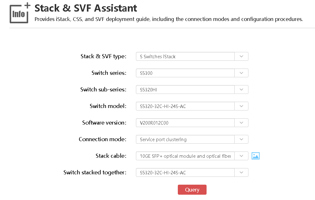
round-trip min/avg/max = 47/71/94 msHuawei Stack & SVF Assistant
huawei’nin support sayfaları arasında huawei network ekipmanlarının stack bağlantılarında yardımcı olacak bir araç mevcut.
http://support.huawei.com/onlinetoolsweb/virtual/index?lang=en&domain=1
Oktay hocam söylerde paylaşmaz mıyım hiç 🙂