huawei network ekipmanlarında alarm nedeniyle kapanmış olan arayüzlerin açılması
bir çok router ve switchte herhangi bir arayüz üzerindeki servislerde veya portta fiziksel hataların tespiti ile o arayüz üzerindeki servislerin / trafiğin daha fazla etkilenmemesi için arayüzü kapatabilirsiniz.
huawei network ekipmanlarında benzer şekilde kapatılmış arayüzlerin tespitini yapmak için farklı yöntemler mevcut.
display trapbuffer ve display logbuffer ile log incelemesi yapılabilir. display interface brief ile loop v.b. durumlar gözlemlenebilir.
en temel olanı ise arayüze doğrudan bakmak.
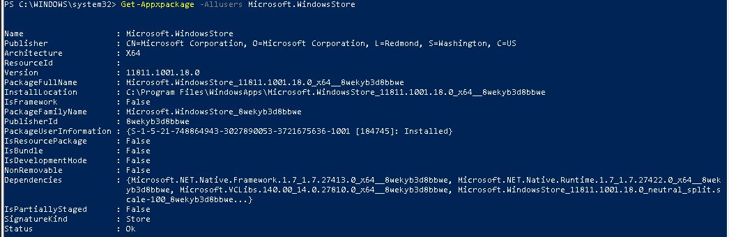
[test_router-GigabitEthernet1/0/1]display interface GigabitEthernet 1/0/1
GigabitEthernet1/0/1 current state : Port-alarm DOWN
Line protocol current state : DOWN
Link quality grade : --
Description:test-interface
Route Port,The Maximum Transmit Unit is 9212
Internet Address is 11.12.13.17/31
IP Sending Frames' Format is PKTFMT_ETHNT_2, Hardware address is bc3d-39ef-f236
The Vendor PN is MTRS-02X13-G
The Vendor Name is HG GENUINE
Port BW: 10G, Transceiver max BW: 10G, Transceiver Mode: SingleMode
WaveLength: 1310nm, Transmission Distance: 10km
Rx Power: -2.09dBm, Warning range: [-14.40,  0.50]dBm
Tx Power: -40.00dBm, Warning range: [-8.20,  0.50]dBm
Loopback:none, LAN full-duplex mode, Pause Flowcontrol:Receive Enable and Send Enable
Last physical up time   : 2020-08-22 14:27:21 UTC+03:00
Last physical down time : 2020-08-22 14:27:23 UTC+03:00
Current system time: 2020-08-22 17:31:33+03:00
Statistics last cleared:2020-08-22 16:32:36
    Last 10 seconds input rate: 0 bits/sec, 0 packets/sec
    Last 10 seconds output rate: 0 bits/sec, 0 packets/sec
    Input: 0 bytes, 0 packets
    Output: 0 bytes, 0 packets
    Input:
      Unicast: 0 packets, Multicast: 0 packets
      Broadcast: 0 packets, JumboOctets: 0 packets
      CRC: 0 packets, Symbol: 0 packets
      Overrun: 0 packets, InRangeLength: 0 packets
      LongPacket: 0 packets, Jabber: 0 packets, Alignment: 0 packets
      Fragment: 0 packets, Undersized Frame: 0 packets
      RxPause: 0 packets
    Output:
      Unicast: 0 packets, Multicast: 0 packets
      Broadcast: 0 packets, JumboOctets: 0 packets
      Lost: 0 packets, Overflow: 0 packets, Underrun: 0 packets
      System: 0 packets, Overrun: 0 packets
      TxPause: 0 packets
      Unknown Vlan: 0 packets
    Input bandwidth utilization  :    0%
    Output bandwidth utilization :    0%
veya
[test_router-GigabitEthernet1/0/1]display interface phy-option GigabitEthernet 1/0/1
GigabitEthernet1/0/1
Port Physical Status    :DOWN
Physical Down Reason    :PORT_ALARM_DOWN
Loopback                :none
Duplex mode             :full-duplex
Pause Flowcontrol:
Receive                 :Enable
Send                    :Enable
SFP imformation:
The Vendor PN is MTRS-02X13-G
The Vendor Name is HG GENUINE
Port BW: 10G, Transceiver max BW: 10G, Transceiver Mode: SingleMode
WaveLength: 1310nm, Transmission Distance: 10km
Rx Power: -2.08dBm, Warning range: [-14.40,  0.50]dBm
Tx Power: -40.00dBm, Warning range: [-8.20,  0.50]dBm
yukarıdaki örneklerde
GigabitEthernet1/0/1 current state : Port-alarm DOWN
Tx Power: -40.00dBm, Warning range: [-8.20,  0.50]dBm

Port Physical Status    :DOWN
Physical Down Reason    :PORT_ALARM_DOWN
arayüzün alarm nedeniyle down olduğu ve doğal olarak tx = -40 olduğu görülmektedir.
bu örnekte arayüz altında hata olmadığı görülüyor. alarmlar temizlenmiş v.b. olabilir. arayüzün neden kapanmış olduğuna bakalım.
[test_router-GigabitEthernet1/0/1]display  port-error-info  interface GigabitEthernet 1/0/1
GigabitEthernet1/0/1 port-error information
================================================================================
 input-error                            | output-error
--------------------------------------------------------------------------------
 trap enable    : Yes                   | trap enable    : Yes
 trigger down   : No                    | trigger down   : No
 alarm status   : No                    | alarm status   : No
 threshold high : 1000                  | threshold high : 1000
 threshold low  : 100                   | threshold low  : 100
 interval       : 10    sec.            | interval       : 10    sec.
 stat(h)        : 0                     | stat(h)        : 0
 stat(l)        : 0                     | stat(l)        : 0
================================================================================
 crc-error                              | symbol-error
--------------------------------------------------------------------------------
 trap enable    : Yes                   | trap enable    : Yes
 trigger down   : Yes                   | trigger down   : No
 alarm status   : No                    | alarm status   : No
 threshold high : 3                     | threshold high : 1000
 threshold low  : 3                     | threshold low  : 100
 percent        : 0                     | N/A            : N/A
 interval       : 10    sec.            | interval       : 10    sec.
 stat(h)        : 0                     | stat(h)        : 0
 stat(l)        : 0                     | stat(l)        : 0
[test_router-GigabitEthernet1/0/1]
arayüz için 4 alarm kontrolün aktif olduğu görülmektedir. çıktıya baktığımızda
crc-error
trap enable    : Yes
trigger down   : Yes
crc hataları nedeniyle tetiklendiği görülmektedir. ilk önce portun kapanmasına neden olan alarmlar giderilmeli. alarm nedeni giderildikten sonra yapılması gereken için port üzerindeki alarmların clear edilmesi gerekmekte.
bunun nasıl yapılacağını
huawei routerlarda interface üzerinde alarm sayısını sıfırlama
başlıklı yazıda yazmıştım. alarmları sıfırladıktan sonra arayüzün aktif hala gelmesi gerekiyor. eğer aktif olmaz ise portu restart yapmak faydalı olabilir.
[test_router-GigabitEthernet1/0/1]restart